O-Ring Installation Design and Specification For Dynamic / Reciprocating Applications
The following chart gives typical gland dimensions for common o-ring sizes within reciprocating / dynamic applications. Please consult with your o-ring manufacturer for custom or application specific requirements.
To use this document, first identify if you have a rod or piston application gland requirement. From the chart below, identify your nominal o-ring desired size, then your o-ring gland depth requirements. After you have verified your nominal o-ring size functionality within your assembly, specify / design your o-ring groove/gland.
Piston / Rod O-Ring Gland / Groove Installation
For male / piston application : For female / rod application: GD = FDmax - 2Lmax Where: GD = Gland diameter |
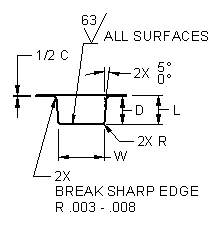
O-Ring Gland / Groove Detail
 |
Where: W = Width at bottom surface intersection of groove |
Typical Reciprocating / Dynamic O-Ring Static Seal Glands / Grooves
See "Gland / Groove Detail" above
O-Ring Nominal Diameter |
Actual Diameter (1) |
Gland Depth (L) |
Compression Actual |
Compression % |
Gland / Groove Width (W) |
Groove Radius (R) |
Total Runout Maximum (TR) |
Total Runout Maximum GD relative to FD |
1/16 |
.070± .003 |
.055 to .057 |
.010 |
15 to 25 |
.093 to .089 |
.005 to .015 |
.0010 |
.002 |
3/32 |
.103± .003 |
.088 to .090 |
.010 to .018 |
10 to 17 |
.140 to .145 |
.005 to .015 |
.0010 |
.002 |
1/8 |
.138± .004
|
.121 to .123 |
.012 to .022 |
9 to 16 |
.187 to .192 |
.010 to .025 |
.0015 |
.003 |
3/16 |
.210± .005
|
.185 to .188 |
.017 to .030 |
8 to 14 |
.281 |
.020 to .035 |
.002 |
.004 |
1/4 |
.275± .006
|
.237 to .240 |
.029 to .044 |
11 to 16 |
.375 to .380 |
.020 to .035 |
.0025 |
.005 |
(1) May vary between different o-ring manufacturers
Related:
- Rubber Molding Design Guidelines and Review
- O-Ring, Design Considerations General
- O-Ring Installation, Design & Specification Gland (Groove) Sizes Static Cylindrical Applications
- O-Ring Installation, Design & Specification Gland (Groove) Sizes Static Flange Application
- O-Ring Installation Compressive Load vs Hardness Chart .070 Diameter ORing
- O-Ring Installation Compressive Load vs Hardness Chart .103 Diameter ORing
- O-Ring Installation Compressive Load vs Hardness Chart .139 Diameter ORing
- O-Ring Installation Compressive Load vs Hardness Chart .210 Diameter ORing
- O-Ring Installation Compressive Load vs Hardness Chart .275 Diameter ORing
