Related Resources: calculators
Pipe Straight Pipe or Large Bends Stress Calculator and Equations
Hydraulic & Pneumatics
Fluids Flow Design and Engineering
The nominal bending stress in a straight pipe or large radius bends due to weight or other external load calculator.
Preview: Pipe Bending Straight Pipe or Large Bends Stress Calculator
Pipe Bending Stress due to Weight or other External Loads is:
Eq. 1SB = M / Z
The nominal bending stress in fittings and components due to weight or other external loads is:
Eq. 2
SB = MR / Z
Resultant intensified moment across the fitting or component. The resultant moment shall be calculated as:
Eq. 3
MR = [ ( 0.75 ii Mi )2 + ( 0.75 io Mo )2 + Mt 2 ]1/2
Eq. 4
Z = 1 / I
Eq. 5 (area moment of inertia pipe)
I = π ( D4 - d4 ) / 64
Eq. 6 (section modulus pipe)
Z = π ( D4 - d4 ) / ( 32 D )
Where
M = the bending moment across the pipe cross section, lb-in, (N-m)
Z = The pipe section modulus, in3 (m3)
ii = in-plane stress intensification factor
io = out-of-plane stress intensification factor
Mi = in-plane bending moment, lb-in. (N-m)
Mo =out-of-plane bending moment, lb-in. (N-m)
Mt = torsional moment, lb-in (N-m)
D = outer diameter, in (m)
d = inner diameter, in (m)

Figure 1, Pipe Data
If a section of pipe can operate either warmer or colder than the installed temperature, both conditions to T2 may need to be examined.
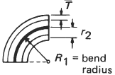
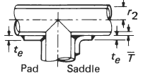
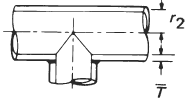
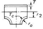
Table 1, Stress Intensification Factor, i per. ASME B31.8
Description |
Out of Plane io |
In-Plane ii |
Sketch |
Welding elbow or pipe bend |
0.75 / h2/3 |
0.90 / h2/3 |
 |
Welding tee per |
- |
3/4 io + 1/4 |
 |
Reinforced fabricated tee with pad or saddle |
- |
3/4 io + 1/4 |
 |
Unreinforced fabricated tee |
- |
3/4 io + 1/4 |
 |
Extruded outlet ro ≥ d / 8 Tc < 1.5 |
- |
3/4 io + 1/4 |
 |
Source:
ASME B31.9, Gas Transmission and Distribution Systems
Related
- Pipe Bends Minimum Wall Thickness Calculator per. ASME B31.3
- L Pipe Bend Guided Cantilever Beam Equation and Calculator
- Pipe Stress Due to Sustained Loads Formulae and Calculator
- Pipe Thread Installation Torque Table Chart
- Pipe Support Spacing For Deflection Control Design Calculator
- Allowable Stresses for Pipe and Tube B36.10M
- Thermal Expansion or Contraction of Piping per. ASME B31.8
- Steel Pipe Clamps Stress and Friction Capacity Analysis
- Pressure Vessel Design Formula and Calculators Resources
- Pressure Vessel Pipe Stress Longitudinal Stress (Circumferential Joint) Calculator
- Pipe Thread Installation Torque Table Chart
- Copper Tubing Size Chart ASTM B-88
- Standard Pipe Schedules and Sizes Chart Table Data
- Schedule 80 Steel Pipe Sizes & Dimensions ANSI American National Standard Schedule 80 Welded and Seamless Steel Pipe.
- Schedule 40 Plastic PVC, CPVC Pipe Sizes & Dimensions PVC, CPVC and other Schedule 40 Plastic Pipe.
- Schedule 80 Plastic PVC, CPVC Pipe Sizes & Dimensions American National Standard Schedule 80 Welded and Seamless Steel Pipe.