Related Resources: Fluids Engineering
Liquid Pressure Drop in Pipe and Pipe Fittings Spreadsheet Calculator
NOTE:
- Refunds are not awarded after excel files have been downloaded - review your membership agreement for details.
- This excel spreadsheet may contain macros which will need to be enabled in your excel application, see web page: Enable macros in Downloaded excel files
- Units utilized within calculators are either SI or Imperial (some enable both SI and Imperial) and member (you) are responsible for conversions. Ensure that you verify units utilized in excel application meet your requirements before downloading.
Engineering Excel Spreadsheet Downloads
Fluid Flow Design and Engineering
Hydraulic and Pneumatic Design and Engineering
Liquid Pressure Drop in Pipe and Pipe Fittings Spreadsheet Calculator
How the Worksheet Works
There are ten columns of identical individual calculations. You can use just one, or you can use more than one for different flow rates in the same system, for unrelated calculations or for chained calculations for the same system where you want to break the system down into several small systems in series.
In Column C, each variable, constant or formula cell is assigned, as its name, the variable name in Column B, and it is this name that is used whenever that cell's contents are used in a subsequent formula. With this knowledge, the user can easily see the flow of the calculations by studying the worksheet. (This naming of the cells only applies to Column C. When a variable or formula is duplicated in a subsequent column, cells are simply referred to by their cell number, i.e. “D10.”)
In general, the worksheet uses methods presented in “ Flow of Fluid Through Valves, Fittings and Pipe, Technical Paper No. 410 ” published by the Crane Company. Over the years I have found this to be a valuable reference. It can be purchased from the Crane Company. Copy and paste this URL into your browser: www.flowoffluids.com
Crane also has a very comprehensive software package for doing piping calculations which, the last time I checked their web site, they sell for $1,395. (I have no affiliation with the Crane Company and do not benefit from any sales they make.)
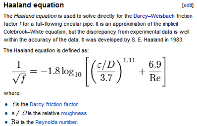
For the calculation of the friction factor the worksheet uses the Haaland equation which gives an implicit solution to the friction factor. The Wikipedia article on "Darcy friction factor formulae" states “The Haaland equation is used to solve directly for the Darcey-Weisbach friction factor f for a full-flowing circular pipe. It is an approximation of the implicit Colebrook-White equation, but the discrepancy from experimental data is well within the accuracy of the data.”
The worksheet follows the convention in the Crane book of using the actual friction factor, f, for determining the “K factor” of pipe, and the turbulent friction factor, f T for determining the “K factor” of fittings.
There is a section for entering a take-off of valves and fittings. In the “K factor VALVES & FITTINGS” section, the total value of the K for each type of fitting is calculated by multiplying the quantity of that type of valve or fitting, by its “L/D” (mostly taken from the Crane book) and by f T . For valves, if you know the actual Cv of the valve, you will get a more accurate K factor by entering the Cv in one of the fields for Cv Valve (1 through 5).
For reducers and expanders (there is only space for one of each) you enter the beta of the element. Beta is defined as the “smaller diameter divided by the larger diameter.”
Using the Worksheet
If you have read the above section, using the worksheet is straight forward. To avoid unsightly clutter and error messages in portions of the sheet that are not being used, calculated results are only shown after all of the required data has been entered. Required fields have a blue background. The fields with a green background are for optional inputs.
The fields for the “VALVE AND FITTING TAKEOFF” are only filled in when they are applicable. If the only thing in a system is pipe and one standard port ball valve you would enter a 1 on Line 22 and leave the rest of the cells in that section empty. The sheet will calculate the K factor of one standard port ball valve of 0.703 on Line 44. If you know the Cv of a valve, it will be more accurate to enter its Cv in one of the valve Cv fields instead of entering a 1 in one of the valve takeoff fields.
Line 65 optionally allows you to enter the K factor (or th e sum of K factors) for any other equipment that is not included elsewhere. An example would be a heat exchanger.
The "Change in elevation" field only needs to be filled in if there is a difference in elevation between the beginning and end of the system. If in addition to the total pressure loss in the system, you want to know the pressure at the end of the system (P 2 ) you can optionally enter the pressure at the beginning of the system (P 1 ) on Row 73.
If you have a system where the pipe size changes, you will need to split the system into two series calculations. The one with the larger pipe will have a reducer or expander. If the reducer or expander went from 4 inches to 2 inches, its Beta would be 0.5.
Equations Used:

Note: Accessing this resource requires an active Premium Membership with Engineers Edge
Download:
Liquid Pressure Drop in Pipe and Pipe Fittings Spreadsheet Calculator