Related Resources: calculators
Orifice Submerged in Liquid Discharge Rate Calculator and Equation
Fluid Flow Engineering and Design
Fluid Flow Hydraulic and Pneumatic Engineering and Design Menu
Orifice Submerged in Liquid Discharge Rate Calculator and Equation
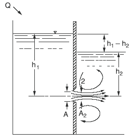
Submerged Orifice Operating under Steady-Flow Conditions
Preview Submerged Orifice Operating under Steady-Flow Conditions
Eq. 1
Q = A2 v2 = Cd Cc Cv Cva A [ 2 g (h1 - h2) ](1/2)
The coefficient of contraction, Cc, accounts for the flow area reduction of the jet caused by the flow curving and springing from the orifice edges. The coefficient Cvaaccounts for the velocity distribution and friction loss. The product, Cc Cva, is sometimes called the coefficient of discharge, Cd. The coefficient Cv accounts for using the water head only and does not fully account for the velocity head of approach. The effective discharge coefficient, Cd , is the product Cd Cc Cv Cva, which has been determined experimentally to be 0.61 for rectangular irrigation weirs. The coefficient of contraction has the most influence on the effective coefficient discharge. Because Cc must approach unity as velocity approaches zero, its value will increase rapidly after reaching some low velocity. Thus, the equation should not be used for heads less than 0.2 ft even with very precise head measuring devices. The difference between upstream and downstream heads or water surface elevations is sometimes called the differential head, can be rewritten as:
Eq. 2
Q = Cd A [ 2 g (h1 - h2)(1/2)
Q = Cd A [ 64.4 (h1 - h2)(1/2)
where
v2 = velocity of fluid exiting orifice
Q = discharge (ft3/s)
Cd = Discharge coefficient
Cc= coefficient of contraction (use 1.0 unless Cd specified)
Cv= coefficient of velocity caused by friction loss (use 1.0 unless Cd specified)
Cva = coefficient to account for exclusion of approach velocity head from the equation (use 1.0 unless Cd specified)
A = the area of the orifice (ft2)
g = acceleration caused by gravity (32.2 ft/s2)
h1 = upstream head (ft)
h1 = downstream head (ft)
Table 1 Variation in the Circular Orifice discharge coefficient, with relative distance from the orifice edge to the upstream and downstream concentric boundary (Adapted from Albertson et. al. 1960)
| Boundary distance | Cd |
Increase in Cd (%) |
| > 10 diameters | 0.61 |
- |
| 1 diameter | 0.62 |
1% |
| 1/2 diameter | 0.65 |
6% |
| 1/4 diameter | 0.68 |
11% |
Table 2 Average discharge coefficients for furrow orifices measured by Rodinson (1959)
Orifice Diameter |
Cd Submerged Flow |
Cd Free flow |
|
mm |
(inches) |
||
| 19.1 |
(3/4) |
0.57 |
0.61 |
| 26.4 |
(1.0) |
0.58 |
0.62 |
| 34.9 |
(1-3/8) |
0.61 |
0.64 |
| 44.5 |
(1-3/4) |
0.61 |
0.63 |
| 50.8 |
(2.00 ) |
0.61 |
0.62 |
| 63.5 |
(2-1/2) |
0.60 |
0.61 |
| 76.2 |
(3.00 ) |
0.60 |
0.60 |
| 88.9 |
(3-1/2) |
0.60 |
0.60 |
| 101.6 |
(4 ) |
0.60 |
0.60 |
Related
- Orifice Plate Flow Calculations and Design
- Orifice Plate Type Flow Detector Review
- Nozzle Venturi and Orifice Flow meter Formula and Calculator
- Gas Flow Rate Through Orifice Equations and Calculator per. ISO 5167
- Discharge of Air Through An Orifice Equation and Calculator
- Velocity Escaping Compressed Air Equation and Calculator
- Fluids Discharge Measurement Structures and Systems
- Time to Drain Vertical Tank Draining Time Formulas and Calculator
- Time to Drain Spherical Tank Draining Time Formulas and Calculator
- Time to Drain Horizontal Tank Draining Time Formulas and Calculator
Source
- United States Department of the Interior Bureau of Reclamation
- Albertson, Maurice L., James R. Barton, and Daryl B. Simons. 1960.
- Fluid mechanics for engineers. Prentice Hall, Inc., Englewood Cliffs, NJ, pp 133 and 136.
- American Society of Mechanical Engineers (ASME). 1959. Fluid meters—their theory and application. American Society of Mechanical Engineers 5th Edition. 19 West 39th St., New York, pp. 69-77.
- Bos, M. G. 1976. Discharge measurement structures. Publication No. 20, International Institute for Land Reclamation and Improvement, Wageningen, The Netherlands.
