Truck and Car Universal Joint Design and Engineering Equation
Power Transmission and Technology Menu
Truck and Car Universal Joint Design and Engineering Equation
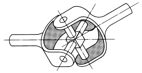
A class of shaft connectors is composed of the linkage types, which include universal joints (U-joints) and rotating-link couplings. These couplings all rely on translating misalignment to relative rotation between parts of the coupling. The simplest universal joint is the one for a compass suspension universal joint described by Geronimo Cardano in the sixteenth century and explained mathematically by Robert Hooke in the seventeenth century. The universal joint basically consists of two shaft connections (yokes) which pivot about a pair of centrally located bearings. See Figure 1.
 .
.
Figure 1
Shafts A and B are inclined to each
other at angle θ (shaft centerlines must
intersect); when shaft A is rotated, the
center member (spider) causes shaft B
to rotate by virtue of the connection.
The output speed of shaft B is not constant
when the shafts are at an angle.
Specifically, the output velocity is:
![]()
Figure 2
where α = rotation position angle and θ = joint or shaft angle. In addition, the change in velocity peaks twice during every revolution. This leads to a second-order harmonic excitation frequency for the drive system. Specifically, the torsional magnitude β of this excitation is:
![]()
Figure 3
The single Hooke’s universal joint is not capable of accepting parallel misalignment (shaft centerlines do not meet at pivot member) except for very minor amounts resulting from manufacturing tolerances. Axial misalignment is usually compensated for by using a sliding connection on the input-output shafts or between the two universal joints.
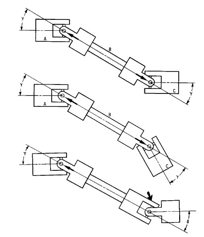
When two universal joints are connected in series, parallel misalignment can be compensated for, because the parallel misalignment is converted to angular in each joint (see Figure 6). By connecting two universal joints in this manner, it is possible to obtain approximately uniform output velocity between A and C. Basically, if joints A and B are aligned such that the pivot pins in their input and output yokes, respectively, are in the same plane, then the nonuniform output of joint A into shaft B is transformed to uniform output in joint C. However, if any angle exists between the joint A input yoke plane and the output yoke plane of joint C, then a nonuniform output will be generated. That nonuniform velocity and angle are, if we refer to Figure 6c,
![]()
Figure 4
where θeff = equivalent torsional angle given by:
![]()
Figure 5
Note that δ and γ are the U-joint angles as given in Figure 6c.

Figure 6
How two universal joints convert angular misalignment to parallel misalignment.
(a),
(b) Correct, yoke ears are
aligned and angles are equal.
(c) Incorrect, yoke ears are not in
alignment and angles γ and δ are not equal. A residual angle θeff
results from improper phasing of the two universal joints.