Open End Engineers Wrench 15° Installation Design Clearance Sizes Table Chart
General Engineering Reviews
Engineering Applications and Design
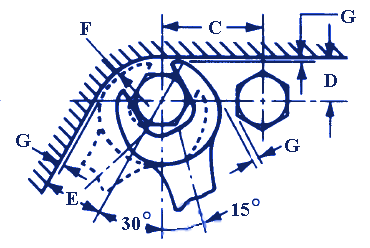
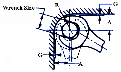
Open End Engineers Wrench 15° Installation Design Clearance Sizes - Wrench Clearance Chart data derived from SAE drafting manual and ANSI/ASME B18.2.2-1987 (R1999) wrench opining for nuts/bolts. This represents the recommended installation clearances for standard 15 degree open end wrenches.
|
 120 Degree + Installation |
Note: All dimensions are in inches
Wrench Size |
Bolt Center Wall Clearance Minimum A |
Wall Radius Maximum B |
Minimum Bolt Spacing C |
Bolt Center Wall Clearance Minimum D |
|---|---|---|---|---|
.156 |
.220 |
.250 |
.390 |
.160 |
.188 |
.250 |
.280 |
.430 |
.190 |
.250 |
.280 |
.340 |
.530 |
.270 |
.312 |
.380 |
.470 |
.660 |
.280 |
.344 |
.420 |
.500 |
.750 |
.340 |
| .375 |
.420 |
.500 |
.780 |
.360 |
.438 |
.470 |
.590 |
.890 |
.420 |
.500 |
.520 |
.640 |
1.000 |
.470 |
.562 |
.590 |
.770 |
1.130 |
.520 |
.594 |
.640 |
.830 |
1.210 |
.530 |
.625 |
.640 |
.830 |
1.230 |
.550 |
.688 |
.770 |
.920 |
1.470 |
.660 |
.750 |
.770 |
.920 |
1.510 |
.670 |
.781 |
.830 |
.950 |
1.550 |
.690 |
.812 |
.910 |
1.120 |
1.660 |
.720 |
.875 |
.970 |
1.150 |
1.810 |
.800 |
.938 |
.970 |
1.150 |
1.850 |
.810 |
1.000 |
1.050 |
1.230 |
2.000 |
.880 |
1.062 |
1.090 |
1.250 |
2.100 |
.970 |
1.125 |
1.140 |
1.370 |
2.210 |
1.000 |
1.250 |
1.270 |
1.420 |
2.440 |
1.080 |
1.312 |
1.390 |
1.690 |
2.630 |
1.170 |
1.438 |
1.470 |
1.720 |
2.800 |
1.250 |
| 1.500 |
1.470 |
1.720 |
2.840 |
1.270 |
1.625 |
1.560 |
1.880 |
3.100 |
1.380 |
Wrench Size |
Bolt Center Wall Clearance Minimum E |
Wall Radius Maximum F |
Reference Wrench End Clearance G |
Wrench Thickness or Width Maximum H |
|---|---|---|---|---|
.156 |
.250 |
.200 |
.030 |
.094 |
.188 |
.270 |
.230 |
.030 |
.172 |
.250 |
.310 |
.310 |
.030 |
.172 |
.312 |
.390 |
.390 |
.050 |
.203 |
.344 |
.450 |
.450 |
.050 |
.203 |
| .375 |
.450 |
.520 |
.050 |
.219 |
.438 |
.520 |
.640 |
.050 |
.250 |
.500 |
.580 |
.660 |
.050 |
.266 |
.562 |
.660 |
.700 |
.050 |
.297 |
.594 |
.700 |
.700 |
.050 |
.344 |
.625 |
.700 |
.700 |
.050 |
.344 |
.688 |
.880 |
.800 |
.060 |
.375 |
.750 |
.880 |
.800 |
.060 |
.375 |
.781 |
.890 |
.840 |
.060 |
.375 |
.812 |
.970 |
.860 |
.060 |
.406 |
.875 |
1.060 |
.910 |
.060 |
.438 |
.938 |
1.060 |
.950 |
.060 |
.438 |
1.000 |
1.160 |
1.060 |
.060 |
.500 |
1.062 |
1.200 |
1.200 |
.080 |
.500 |
1.125 |
1.270 |
1.230 |
.080 |
.500 |
1.250 |
1.390 |
1.310 |
.080 |
.562 |
1.312 |
1.520 |
1.340 |
.080 |
.562 |
1.438 |
1.590 |
1.340 |
.090 |
.641 |
| 1.500 |
1.590 |
1.450 |
.090 |
.641 |
1.625 |
1.750 |
1.560 |
.090 |
.641 |
Related:
- SAE 12 Point Box Wrench Clearance Sizes Table Chart
- ISO Metric Wrench Bolt Size Table Chart
- Wrench Openings Table
- Torque Wrench Adapter for Reduced Arm Equation and Calculation
- Open End Engineers Wrench 15° Installation Design Clearance Sizes Table Chart
- Torque Wrench Calculator for Extended Adapter with Formulas
- Hydraulic and Pneumatic Torque Wrenches Application Review
