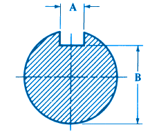
Shaft Arbor and Keyseat Dimensional Design Data - ANSI/ASME B94.19 American National Standard Keys and Keyways
The following is summarized from the American National Standard Keys and Keyways for Milling Cutters and Arbors ANSI/ASME B94.19
Shaft and Arbor Class A and B

Nominal Shaft (Arbor) and Keyseat Cutter Hole Diameter |
ARBOR AND KEYSEAT | ||||
Nominal Size |
Arbor and Keyseat |
||||
| A | A | B | B | ||
|---|---|---|---|---|---|
| Max. | Min. | Max. | Min. | ||
1⁄2 |
3⁄32 | 0.0947 | 0.0937 | 0.4531 | 0.4481 |
5⁄8 |
1⁄8 | 0.1260 | 0.1250 | 0.5625 | 0.5575 |
3⁄4 |
1⁄8 | 0.1260 | 0.1250 | 0.6875 | 0.6825 |
7⁄8 |
1⁄8 | 0.1260 | 0.1250 | 0.8125 | 0.8075 |
1 |
1⁄4 | 0.2510 | 0.2500 | 0.8438 | 0.8388 |
11⁄4 |
5⁄16 | 0.3135 | 0.3125 | 1.0630 | 1.0580 |
11⁄2 |
3⁄8 | 0.3760 | 0.3750 | 1.2810 | 1.2760 |
13⁄4 |
7⁄16 | 0.4385 | 0.4375 | 1.5000 | 1.4950 |
2 |
1⁄2 | 0.5010 | 0.5000 | 1.6870 | 1.6820 |
21⁄2 |
5⁄8 | 0.6260 | 0.6250 | 2.0940 | 2.0890 |
3 |
3⁄4 | 0.7510 | 0.7500 | 2.5000 | 2.4950 |
31⁄2 |
7⁄8 | 0.8760 | 0.8750 | 3.0000 | 2.9950 |
4 |
1 | 1.0010 | 1.0000 | 3.3750 | 3.3700 |
41⁄2 |
11⁄8 | 1.1260 | 1.1250 | 3.8130 | 3.8080 |
5 |
11⁄4 | 1.2510 | 1.2500 | 4.2500 | 4.2450 |
All dimensions given in inches.
Related:
- Standard Metric Keys Keyways for Metric Bores with One Key
- Keyway Cutter Hole Keyway Dimensional Data for MIlling Centers and Arbors - ANSI/ASME B94.19-1997
- Keyway Stresses for Non-metallic Gears and Shafts Formulas and Calculator
- Shaft (Arbor) Keyway Dimensionl Data - ANSI/ASME B94.19-1997
- Design of Square Key and Keyway (Wood Ruff) Stress, Shear and Torque
- Metric Key Keyway Dimensions
- Parallel Key and Taper Keys Dimensions
- Shaft with Keyway Torque Applied Deformation and Stress Equations and Calculator
- Shaft with Two Keyways Torque Applied Deformation and Stress Equations and Calculator