Related Resources: calculators
Pipe per. Threads EN 10226-1 Calculator
Pipe Threads for Pressure Joints per. EN 10226-1 Calculator
EN 10226 specifies the requirements for thread form, dimensions, tolerances and designation for jointing pipe threads, sizes 1/6 to 6 inclusive, for joints made pressure-tight by the mating of the threads. These threads are taper external and parallel internal and are intended for use with pipes suitable for threading and for valves, fittings's or other pipeline equipment interconnected by threaded joints.
Note:
The main dimensions were covered into millimetres on the basis of 1 inch = 25,4 mm, beginning with the number of threads per inc, which determines the pitch P, the formula h (the height of thread) = 0,640327 P and the major diameter at the gauge plane. Pitch diameter and minor diameter then compiled by subtracting once or twice respectively the height of thread h from the major diameter. The nominal gauge length, the tolerances and the assembly length were directly computed. The remaining lengths given in table 1 were obtained by subtracting or adding the tolerances or assembly length respectively to the nominal gauge length. Tolerance and assembly lengths are expressed in millimetres and in number of turns of thread.
a For parallel internally threaded parts the diametral tolerances are derived from the tolerances in the calculator denoted with d by multiplying with the corresponding pitch in the calculator denoted by e and with 1/16, the amount to taper.
b informative tolerances, in millimetres, are obtained from the mandatory values in turns of threads by multiplying with the corresponding pitch denoted as e and rounding to the nearest 0,1 mm.

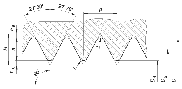
Parallel Thread (Internal)
Where:
P = pitch
H = 0,960491 P
h = 0,640327 P
r = 0,137329 P

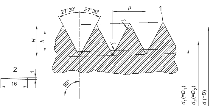
Taper thread (external)
Where:
1 = gauge plane
2 = taper
P = Pitch
H = 0,960237 P
h = 0,640327 P
r = 0,137278 P
Source:
EN 10226-1
Related
- Pipe Thread Installation Torque Table Chart
- National Standard Taper Pipe Threads Size NPT Chart
- Straight Pipe Threads Table Chart ANSI
- Pipe Thread Tap and Drill Size Chart ANSI NPT
- Internal British ISO Pipe Threads (Whitworth Form) Table per. BS EN ISO 228
- External British Pipe Threads (Whitworth Form) Table per. BS EN ISO 228
- Whitworth BS Pipe Thread Size and Tap Drill Table Chart DIN/ISO 228
- API Tubing Engineering Table Chart API Tubing Engineering Table Chart
- API Tubing Grade & Specifications The following guidelines apply to the use of API tubing grades.
- API Casing 4.500 - 5.000 Dia. Engineering Data Table Specification 5C3 of the American Petroleum Institute standardizes 14 casing sizes from 4.5 inches (11.43 cm) to 20 inches (50.80 cm) outside diameter
- API Casing 5.000 - 5.500 Dia. Engineering Data Table API Casing Data Tables sizes 5.00 - 5.50.
- API Casing 5.500 - 6.625 Dia. Engineering Data Table API Casing Data Tables sizes 5.50 - 6.625.
- API Casing 6.625 - 7.000 Dia. Engineering Data Table API Casing Data Tables sizes 6.625 - 7.000 Dia.
- API Casing 7.000 - 7.625 Dia. Engineering Data Table API Casing 7.000 - 7.625 Dia. Table
- API Casing 7.625 Dia. Engineering Data Table API Casing 7.625 Dia. Table
- API Casing 7.625 - 8.625 Dia. Engineering Data Table API Casing 7.625 - 8.625 Dia. Table
- API Casing 9.625 - 10.750 Dia. Engineering Data Table PI Casing 9.625 - 10.750 Dia. Table
- API Casing 10.750 Dia. Engineering Data Table API Casing 10.750 Dia. Table
- API Casing 10.750 - 11.750 Dia. Engineering Data Table PI Casing 10.750 - 11.750 Dia. Table
- API Casing 11.750 - 13.375 Dia. Engineering Data Table API Casing 11.750 - 13.375 Dia. Table
- API Casing 13.500 - 18.375 Dia. Engineering Data Table API Casing 13.500 - 18.375 Dia. Table
- Pipe Thermal Expansion U Shape Loop Equations and Calculator for Pipe Thermal expansion will occur between all fixed points in a piping system. If the system has the same covering height, natural fixed points will occur in the center of a line section between two expansion elbows.